Track Construction
Tribute Site |
|
|
| The Table |
|
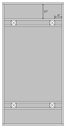
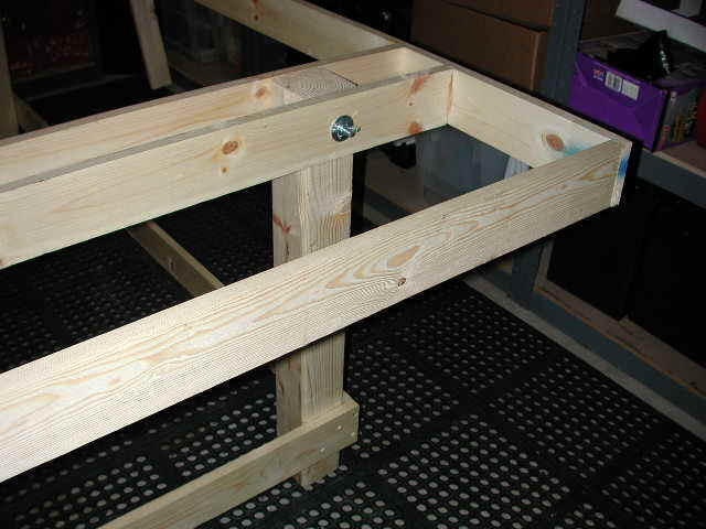
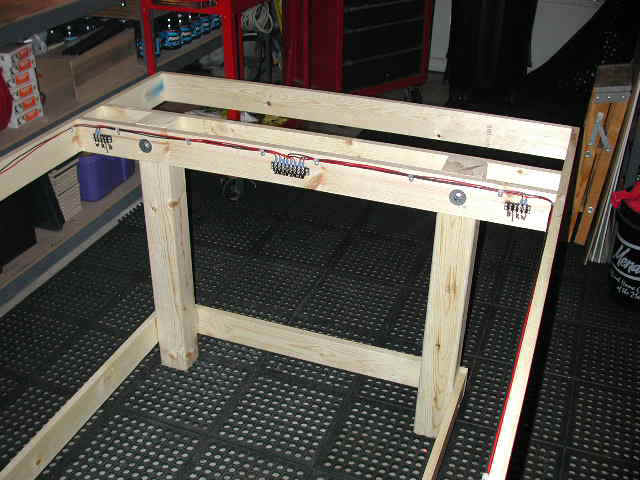
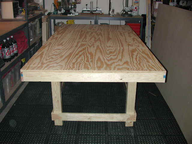
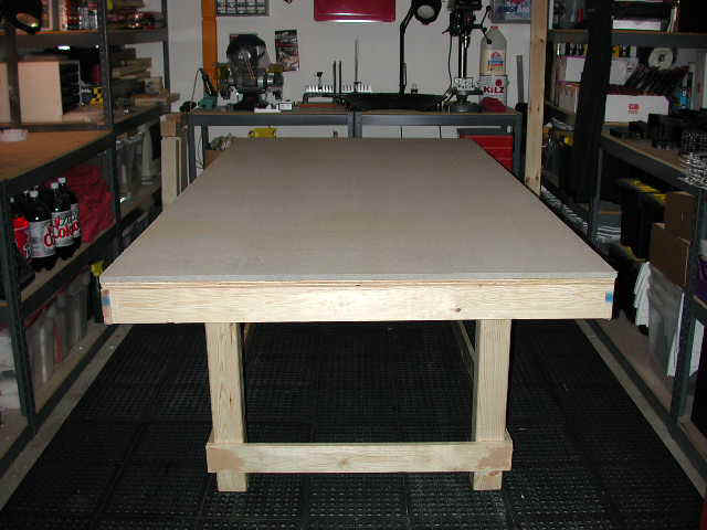
The table for this raceway is my standard 4x8 foot plywood table with 1x4 framing and 4x4 legs. It is the same design as described in the Tables section. The other table sizes described there use the same construction principles as the table illustrated here. Simply extend the length and width if you will be building one of the larger tables described there. |
|
|
|

|
|
|
|
|
|
|
|
|
|
|
|
|
|
|
|
|

|
|
|
|
Here's a complete inventory of what was required to build this 4x8 foot table. |
|
|
|
† 1x8 inch dimensional lumber should be used for the side retaining walls. The table pictured above used 1x6 inch lumber, but that was only because the customer requested it. |
| The Track |
|
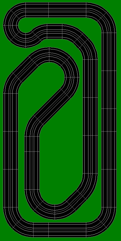
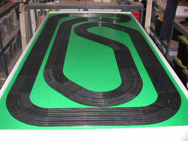
The layout selected for this project is my standard 4x8 foot 4-lane raceway built entirely from Tomy AFX track sections. It provides a fast lap with a challenging infield section. This is the same raceway that appears on the For Sale page. |
|
|
|
|
Here's an inventory of the Tomy AFX track sections required to build this raceway: |
|
|
|
|

|
|
|
|
|
|

|
|
|
| Track Mounting |
|
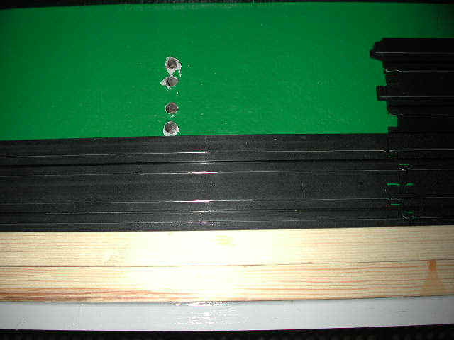
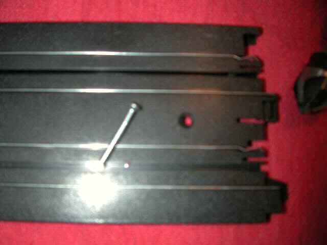
Now it's time to begin mounting the track to the table. I like to start with the longest straight. The overall size of the track itself provides a 1-½" border on all for sides of the table. 1x4 dimensional lumber is actually ¾" when finished, so two pieces laid flat against the side of the retaining wall provide a perfect straight edge for track mounting. Track can simply be butted up against the 1-½" sandwich to assure perfect alignment. |

|
|
|
|
|
|

|
|
|
|
|
|
|
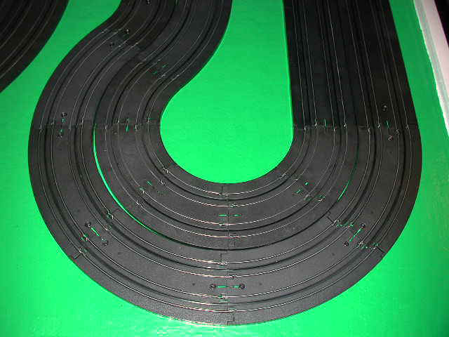
Pay close attention to the track joints as you work. You don't want any large gaps between track joints that would cause the car to bounce as it passes over a joint. I normally countersink holes in 3-4 sections of track at a time and then carefully fasten them using the wood screws. Don't fasten them down to tightly though, just enough to make a secure and flush joint. |
|
|
|
| Lap Timer 2000 Installation |
|
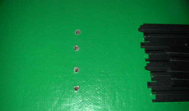
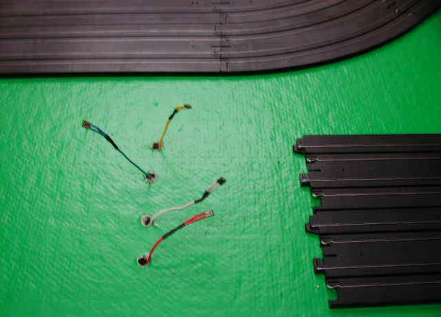
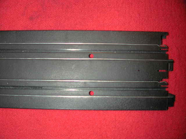
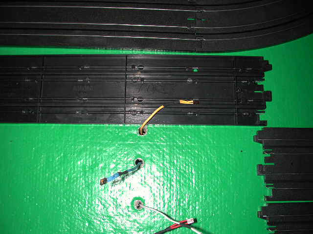
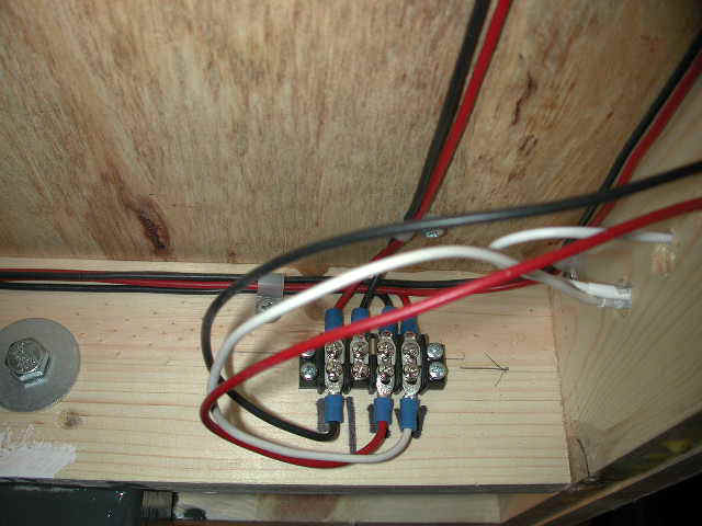
My Lap Timer 2000 4-Lane Interface Kit is also being installed on this track. The kit includes four (4) photo-cells that are to be placed under the track. The photo-cell leads are run to a small junction box that will be mounted under the table in a later step. |

|
|
The photograph above shows the photo-cell sensor assembly and the junction box that will be mounted under the table. Standard HOPRA lane color-coding is used to simplify the installation. |
|
|
|
On this particular track lane 1 is the outside lane closest to the driver's stations, while lane 4 is the inner-most lane. |
|
|
|
|
|
|
|
|
|
|
|
|
| Track Wiring |
|
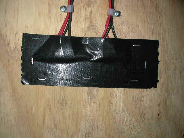
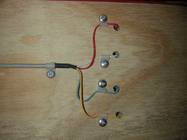
Now it's time to wire the power tracks and hook up the driver's stations. The remaining track wiring all needs to be done from under the table. If you have an automotive creeper use it. Also try to have everything you'll need under the table with you, otherwise you'll be forever climbing out from under the table to retrieve tools and supplies. |

|
|
|
|
|
|
|
|
|

|
|
|
|
|
|
|
|
|
|
|
|
|
|
|

|
|
|
|
|
|
|
|
| Track Landscaping |
|
The track as described above is now ready for day-to-day racing. If you would like to add authenticity to your layout though, you may want to consider landscaping. See the Landscaping section of this web site for detailed information and step-by-step instructions for creating a raceway that looks like an actual race track. |